Build a low cost 6.5 digital voltage meter
I got some low cost VFDs, and also get a paperbox after my phone repaired by the Apple's service. I want to use them to build something, maybe a clock, or a thermometer, but due to VFD need high current power consuption, I decide to use them to build a voltage meter.


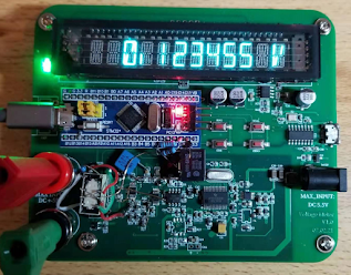
And here is the final view:

Then i want to check it's accuracy, I need a calibrator, thus I found an old Fluke 343A on Ebay Kleinanzeign, after paied the seller 400Euro the seller disappers, he is a cheater, I never imaged a cheater will sell such rare things, build in 1980s. I thought normally they will sell iphone, computers 💔
Then I need to find a low cost test method since I don't have much budget for my hobby activities.
I bought several Max6225 reference chips, and put one into Candy's metal can to avoid the influnce from airflow.
The measurement result looks good, and also the bipolar symmetrical perfect, which indicate a low bias current for the input stage.


In order to test the resolution, I use a potentiometer to generate a nice value, 1.234567V.


It looks not bad, then I use 2PCs 20K resistor as voltage divider, then logging the measurment voltage for one night, the heating is off.

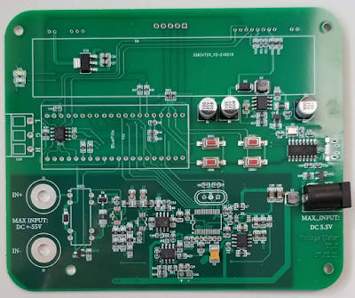
I will make a PCB version for this voltmeter with a higher input range. If many people interested in this topic, I will post the schematical.
评论
发表评论